Measuring in 3D models with Navisworks
Measurements can be made linearly and angularly in areas, and the shortest distance between two objects can automatically be calculated. A point can only register by clicking on an item's point. You click on the background no point registers. If you are in the Scene View, you can right-click instead of left-clicking to reset a command. Measurement restarts with no point register, just like selecting a new measurement type.
Scene View represents endpoints of standard measuring lines as small cross symbols and all lines to measure as simple lines between registered points. Those measuring lines whose endpoints snap to the center line are marked with a cross symbol and another CL marker. The Scene View lets you change the color and thickness of the measuring lines, as well as toggling the display of the dimension labels.
Dimension label
Every segment of a line labels with a dimension label for distance measurements. The latest accumulative measurement segment measures the following dimensions. The total of each dimension is calculated. The text has a centerline.
An invisible line bisects the angle at the intersection of the measuring arc and the center of the text. In cases of excessive acuity, the label will draw outside the angle. The arc label on this screen remains the same size regardless of zoom level unless the measuring lines on the screen become too short for the arc to fit on the screen, in which case it will resize.
Toggling the size labels on and off can be accomplished through the Options Editor.
The dimension label identifies the area that is measuring and placing in the center of that area.
Converting Measurements to Redline
It is possible to convert measurements to redline. Measurements are clear in redlining, and the lines take on the color and diameter specified for redlining.
Redlines were created in the current viewpoint when measurements convert to redlines.
Measure Tool
A measure tool lets you move and rotate currently selected objects. Models can measure between points using measurement tools. Display units are used for all measurements. On the Review tab, select the Measure panel to access the measurement tools. It is impossible to use measurement tools if you are navigating and vice versa.
Measure Tools Window
In this dock-able window, you can view the result of your measurements while working in the Scene View. Each measurement outputs the coordinates of the Start Point and the Endpoint along with the Absolute Distance and the Difference. Distance displays the accumulated distance of all points registered during the measurement if you select an accumulative measure, such as Point Line or Accumulate. 2D sheets do not have Z coordinates.
Locking Feature
If you want to measure in a specific direction or area, lock the line to prevent it from being moved. You may have difficulty measuring accurately when some object geometry interferes. The locking method ensures the first point you measure is a consistent position within the measured geometry. The X-axis can be locked, or a parallel alignment to an object's surface can lock. Based on what kind of lock you use, measure lines change colors. Switching between locking modes can be performed by pressing the shortcut keys when measuring multiple points. 2D sheets do not have Z-axis, Parallel, & Perpendicular locks.
Perpendicular Lock
A perpendicular alignment to the start point is locked. Measurement lines are yellow. If you want to measure the height of a room, for instance, use the Perpendicular Lock and Point measure tool.
Parallel Lock
You align your start point in a parallel position. Measuring lines are indicated in magenta. A room's perimeter can be measured with the Area measure tool for example.
X, Y & Z Lock
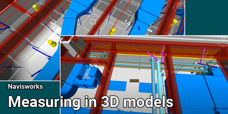
- Red measure lines indicate the X axis, which is horizontal.
- The vertical axis is shown by the green measure line on the Y axis.
- A blue measure line indicates the depth of the z-axis.
The only axis locking options available with 2D sheets are X and Y.